RSS Feeds
|
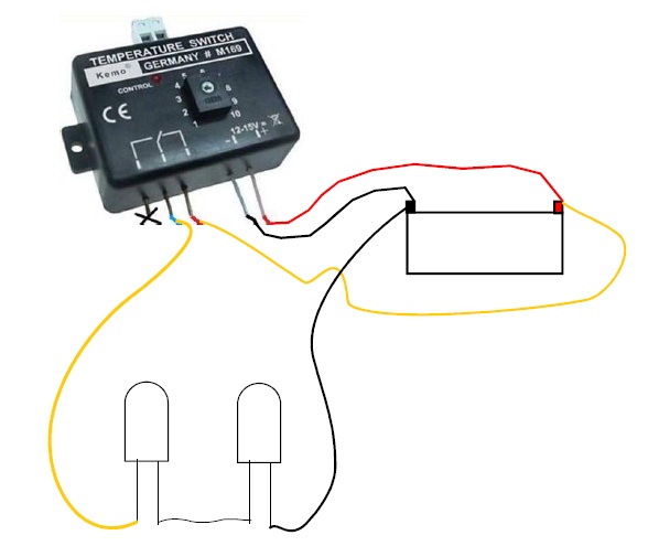
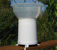
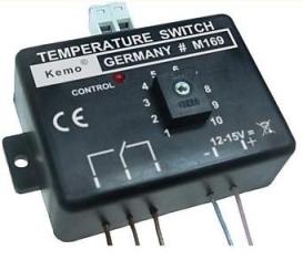
Anemometer Heater Since I've had my Oregon Scientific WMR928 weather station I have had the odd issue with the wind speed freezing during cold weather, (frost and snow). A couple of days ago I came up with an idea for a heater and did some experimenting with a spare anemometer and came up with this idea. It uses 2 wire-ended filament type 12V, 0 08A, 0 96W bulbs, the thinnest wire that will handle the bulbs and a Kemo Temperature Thermostat switch. This setup can run off a 12v battery or a 12v mains PSU. It delivers just the right amount of heat to eliminate any ice and snow build up. You can set the Kemo switch to cut in at what ever temperature suits you, I will have it set at around 2oC once it warms over this temperature then it will turn off the bulbs... Here's how I did it.... Items Needed:
Total cost should be no more than £30 |
 This
section is so you can see what thickness the cable must be! Believe
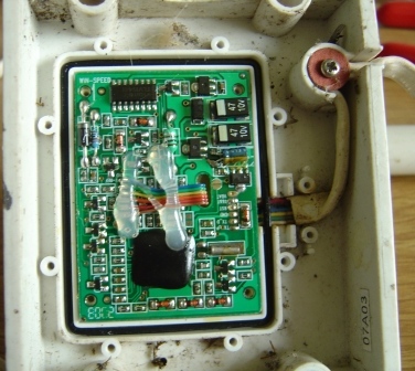
me when I say it needs to be thin.... Ok, Lets start, on the
mounting end, remove the 8 screws holding the cover, then remove the
4 screws holding the PCB, then remove rubber water stop and
the 2 screws holding the cable down and the single screw and
red/brown washer, this is were you need to feed the cable, it has to
follow the existing flat 6 core cable! now you can see why it needs
to be the thin stuff, perhaps removing the outer casing off the
cable will help there, its an option if needs be. You can put a
couple of screws back in for now just to hold it together whilst we
move on...... Now might be a good time to give it a clean.... This
section is so you can see what thickness the cable must be! Believe
me when I say it needs to be thin.... Ok, Lets start, on the
mounting end, remove the 8 screws holding the cover, then remove the
4 screws holding the PCB, then remove rubber water stop and
the 2 screws holding the cable down and the single screw and
red/brown washer, this is were you need to feed the cable, it has to
follow the existing flat 6 core cable! now you can see why it needs
to be the thin stuff, perhaps removing the outer casing off the
cable will help there, its an option if needs be. You can put a
couple of screws back in for now just to hold it together whilst we
move on...... Now might be a good time to give it a clean.... |
|
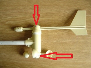
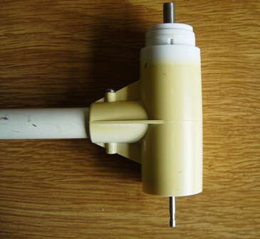
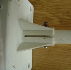
You need to loosen the tightening screws and remove the direction
and the speed units as show in the 1st image below, leaving the
housing as shown in the 2nd image, Then you need to remove the nut
and washer as shown in image 3 below, then remove the screw that is
holding the whole housing to the mounting pole and gently pull the
housing off the pole, as shown in image 4 below...
|
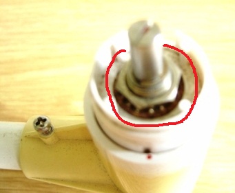
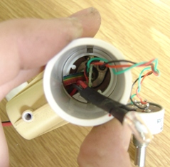
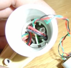
| Now look in the hole where the pole used to be and you will see
a press in clip, See 1st image below, using a screwdriver, push in
the clip and push up and the same time so that you are releasing the
inner sleeve, gently pull out the inner sleeve and the direction
sensor will come out too, you can then gently pull out the small PCB
that has the reed switch on it, NOTE: Be careful when pulling it out
as the reed switch and wires are a little delicate. Now its all
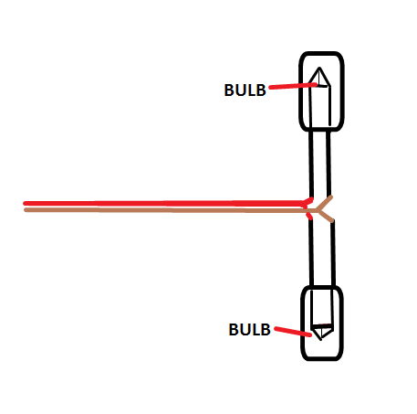
stripped down and ready for the wire with the bulbs attached. You
really need to attach the bulbs to the wire as shown in image 3
below, the reason for this is so that you can have one bulb at the
very bottom of the housing and one behind the small PCB. At this
point you can insulate the back of the PCB where the bulb will go
and the wires for the direction sensor as shown in image 2.
|
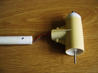
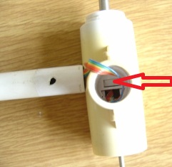
| It will be easier to route the wires by removing the screw
that's in image 1 below and gently pulling the pipe out, Now you
need the thread the wire into the housing and out through the
SAME hole the flat 6 care cable
is through, then through the pipe, pull it all through so your left
with just the bulbs as shown in the 2nd image below (used thicker
wire to show you), Now carefully refit the PCB holder holding the
wires out of the way, make sure it goes all the way to the bottom
else the other sleeve will not click into place. Now carefully push
one bulb OVER the PCB and
down to the bottom of the housing to the metal plate that holds the
speed sensor bearing, then push the other bulb behind the PCB and
pulling any spare cable through the hole so there is NO spare cable
inside the housing at all. see image 3, you can see the bulb behind
the PCB but the 1st bulb is now hidden.
|
 Now to refit the direction spindle and sleeve, note that the direction
spindle unit has a notch, its imperative that this fits into the
hole inside the sleeve, once you have the notch in the hole replace
the washer and bolt, now you need to gently twist the sleeve so that
the excess wires coil back into the sleeve and once done gently
slide it back in to the housing but making sure no wires are being
pinched, pull it back out to check if your unsure, if no wires are
being pinched and the bottom sleeve is in place 100% then the top
sleeve should slide into place and the clip that you released should
not click back into its hole. That's the housing part all done,
don't fit the pole yet, if I was you I would now check the setup to
make sure it all works, temporarily connect the Temperature switch
following all the instructions that came with it, any problems with
the wiring then contact me from the menu on the left. Adjust the
switch to set off the relay and see if the bulbs light up by looking
into the hole where the pipe goes, if its working then disconnect
the switch and carry on....
Now to refit the direction spindle and sleeve, note that the direction
spindle unit has a notch, its imperative that this fits into the
hole inside the sleeve, once you have the notch in the hole replace
the washer and bolt, now you need to gently twist the sleeve so that
the excess wires coil back into the sleeve and once done gently
slide it back in to the housing but making sure no wires are being
pinched, pull it back out to check if your unsure, if no wires are
being pinched and the bottom sleeve is in place 100% then the top
sleeve should slide into place and the clip that you released should
not click back into its hole. That's the housing part all done,
don't fit the pole yet, if I was you I would now check the setup to
make sure it all works, temporarily connect the Temperature switch
following all the instructions that came with it, any problems with
the wiring then contact me from the menu on the left. Adjust the
switch to set off the relay and see if the bulbs light up by looking
into the hole where the pipe goes, if its working then disconnect
the switch and carry on....
|
|
You can now fit the pole back in to the anemometer hosing now, again,
its imperative that you DO NOT
pinch the wires and make sure the holes line up and that there's a
clear line of sight for the screw to be fitted without harming the
wires inside, if there is not clear line of sight then pull it off
again and refit it until your happy the screw will not damage the
wires. If you haven't already done so, remove all screws again so
you can lift up the PCB that's in image 1, now remove the melted
glue from the hole where the flat 6 core wire comes through and
thread your new wire following the path of the flat 6 core cable,
making sure its under the big o-ring and all the way out of the
housing, its this part that will let you know if your wire is thin
enough. Make sure you leave about 8 inches
of slack wire inside the pipe just in case you need to do
any maintenance on the other end in the future, if you don't you
will not be able to pull the other end apart without disassembling
this section again. If your happy with it all then lightly coat the
o-ring with Vaseline/Petroleum jelly, do the same with the rubber
water stop you pulled out earlier, this is to help repel any
water/moisture, then gently screw down the PCB, and the 2 wire stops
and refit the case cover, any screws left over? no doubt pmsl...
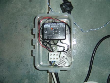
That's about it, refit the temperature switch and use a water proof
housing for it, you can extend the temperature probe by a
MAXIMUM of 1 meter so the switch
unit will need to be close to the anemometer, I would also seal the
probe, I'm sure it says to do that anyway, just follow the
instructions that comes with the switch and you wont go far wrong.
IMPORTANT NOTES:
When wiring up the switch (its normally open) you have to wire it up
so its now normally closed, the reason for this is because in normal
use the switch is used for setting off the relay once it reaches a
higher temperature, but we want it to activate once it
reaches around 2oC (lower temp) so you must wire it so
its normally closed, now the odd part. When used in the normally
open way, the switch activates the relay and the LED on the switch
comes on to let you know its switched, well because of the need to
wire it normally closed, the LED is permanently on until it switches
then it turns off, i think it was an oversight at the
manufacturing stage but it took me around a day to figure out it
still works as needed using the fridge!
|